How To Seal A Box
Errata and Post To-Do’s
The $F$ in the diagrams in the $x-z$ plane below should be $(1-e)F$.
Unfortunately I lost my workings so this post is incomplete, it will be updated when I’m back in the UK.
Introduction
I wasn’t always an engineering student, I used to spend my summers packing boxes in a warehouse where I gained the valuable experience in how to properly seal a box. In my time as a student I have found that most people don’t know how to do this simple task! Especially troubling is that some engineering students (I won’t name names) do not know how to either - or why the best method for sealing works at all above others.
Motivataion
An explanation of the physics behind a simple enough situation such as sealing a box will help in analysing everyday systems that the budding engineer will need to do daily. Plus, while here, I hope you gain some insight on how to actually seal a box.
What’s being used?
We will consider a regular cardboard box with packing tape for the purposes of this discussion. I won’t go into detail on different types of tape as frankly you’re insane if you don’t use packing tape.
Stress and Strain
An important note is that strain in an object cannot exist without a stress. For a spring to be able to take a load, it must strain to elastically accept the load. The same logic applies to regular good old fashioned cardboard and tape!
Plane Stress and Assumptions
We can model the sealing tape as a thin elastic sheet. The tape is assumed to be linear elastic material, and to not have a stress vector act perpendicular to it - this is a plane stress assumption. We can also assume it only takes loads in tension, which is much like one of my favourite fundamental laws of engineering: you can’t push a rope.
By looking at Hooke’s Law, we can see the strain $\varepsilon$ in the tape defines how much load is supported. $$ E = \frac{\sigma}{\varepsilon} = \frac{\frac{F}{A_c}}{\frac{\Delta L}{L}} $$
Parallel Case
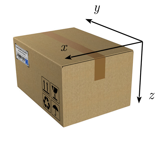
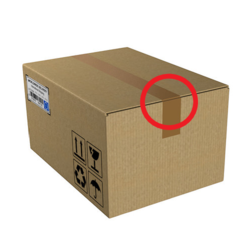
Consider the parallel case, sealed directly inline with the flaps (like this image which I use to define the coordinate system)- the tape supports load along the edge of the box with the highest moment arm meaning the least amount of force is required. The area of interest is at the edge of the box, where the parallel section interfaces with the vertical edge of the box (highlighted here).
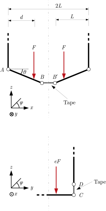
If we look at a simplified diagram of this, we can break down what is happening.
(Vectorised version avaliable here)
If we apply a load $2F$, we can see that the sides of the box take some of the load, as does the tape running along the join. For the walls to take some load there must be a small angle $\theta$ between the wall and the flap. This is because if we assume the structure is pinned, the member $AB$ has tension $T_{AB}$ , with vertical component $T_{AB} \sin (\theta) \approx T_{AB} \theta$.
This implies the tape across $B B^{\prime}$ takes the load $T_{BB^{\prime}} = T_{AB}\cos(\theta)$. By resolving moments we find $Fd = L T_{AB} \sin (\theta) $, rearranged for $T_{AB}$:
$$ T_{AB} = \frac{Fd(1-e)}{L\sin (\theta)} $$
What is $T_{AB}$ in this case? $T_{AB}$’s vertical component resembles the load from $F$ that is not applied through the tape at $CD$, namely what load is transferred to the walls of the box at hinge $A$. The property $e$ is introduced here as a proportion of the load that is put through $CD$.
$$ T_{AB}\sin(\theta) = F - T_{CD} = \frac{Fd}{L} $$
This isn’t very helpful so we consider the tension in the tape:
$$ T_{BB^{\prime}} = \frac{\cot(\theta)Fd(1-e)}{L} \approx \frac{Fd(1-e)}{L\theta} $$
We know that for large $\theta$ our box has failed, as the box stays rigid for only small $\theta$ meaning our small angle assumption is justified.
We can assume strains will be small (implying a nonzero $e$ and a small $\theta$) in an adequately-sealed box, and we will now go on to have a look at the wrong way of sealing the box.
As $\theta$ is a function of $F$ and this section is unfinished and To Be Continued…
Perpendicular Case
In the perpendicular case we have two effects making our situation worse, we have a smaller cross section of tape accross the join $CC^{\prime}$. The strain experienced is over the gap, and by inspection has to be higher to allow the same loads to be supported by the box from the flaps.
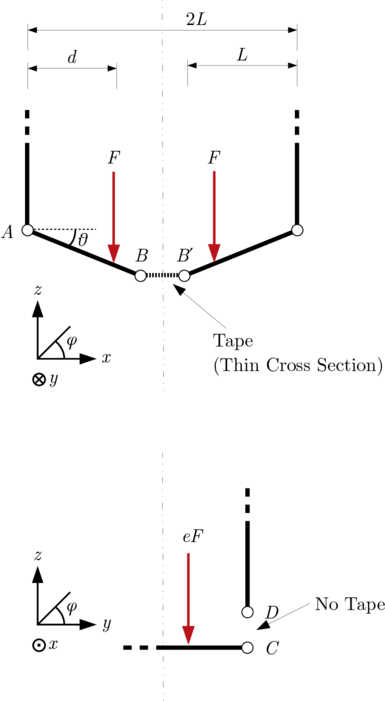
Why is it so? Let’s begin by looking at a diagram:
(Vectorised version avaliable here)
We consider the load vector on the bottom of the box as acting in the z direction, yet by inspection we can see the tape can only support loads in a x direction as there is no tape over $CD$.
We find that the tape never actually takes load in the z direction, even if you wrap it around the box! If we consider the box as a frame - we can see that the members pinned at the edges take all the load in z, the tape merely acts to hold the system together and allow that upward force!
The angle made by the flaps of the box at the bottom allow z loads to be transferred through the cardboard, but require high loads in the tape since the angle is small.
High loads risk the tape failing through the adheisive not being strong enough or the tape yeilding, so clearly the method that doesn’t strictly require any large displacement is preferred.
We have already derived the force distributions, and we know here $e=0$ meaning $ T_{BB^{\prime}} = \frac{\cot(\theta)Fd}{L} $.
We also know since we are going across the join, the cross sectional area $A_{c}$ will be smaller (I shall say ratio 1/R), the stress in the tape will be at least $\frac{R}{1-e_{\mathrm{parallel}}}$ times the stress in the parallel case.
This higher stress implies the tape will fail at lower loads, so this method should not be applied.
Like the above case, $\theta$ is a function of $F$, To Be Continued…
Some Rough Calculations
Since this paper found the Young’s Modulus of tape to be ~270MPa.
To Be Continued…
Happy April Fools Day :)
We will be back in InfoEng and Computers soon!